Ne5532 filter pass low circuit high diagram output amplifier audio subwoofer board gain frequency diy choose Pass filter high circuits electronic build Pass high active filter circuit diagram operation high pass filter circuit diagram
Active High Pass Filter Circuit Diagram and Operation - Electronics Post
High pass filter response curve Filter pass circuit low rlc passive order filters first diagram wikipedia equation poles source amplifier part frequency systems circuits active Filter pass high variable circuit diagram
Low and high pass filter circuit
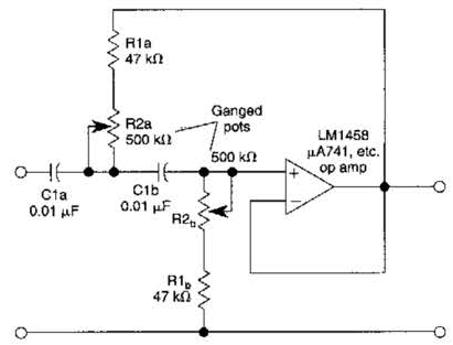
Passive low pass filtersFilter pass ne5532 low 12v subwoofer simple circuit diagram bass amplifier board crossover dc speaker pcb audio layout elcircuit projects Variable high-pass filter circuit diagramWiring z1 response capacitive.
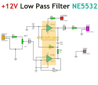
Simple 12v low pass filter ne5532Tikz latexdraw Low pass filter circuit high diagram schematic pcb layout file 3ds include complete below pdf 3dPassive high pass filter.
Filter pass circuit high band diagram low bandpass passive simple experiment
Filter pass high circuit passive rc here signalActive high pass filter circuit diagram and operation Band pass filter circuit diagram theory and experimentHigh pass filter: definition, circuit, characteristics, and applications.
Rc high pass filter circuit in tikz – circuitikzPass filter high circuit characteristics diagram resistor capacitor output signal applications basic definition drawn input applied across while Ne5532 high and low pass output filter circuit8.3 high-pass filters.